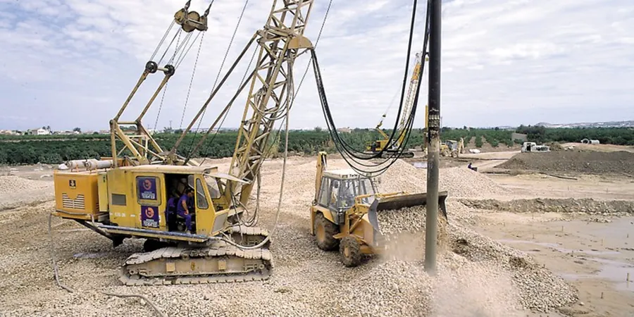
A vibroflot swings off the service crane over a silty clay pad on the east side of McKinney, the 900-mm diameter poker already humming at 1800 rpm. The operator feeds crushed limestone from the loader bucket in controlled lifts, watching the ammeter spike as the stone compacts laterally into the soft Blackland Prairie soil. Stone column design isn't just about picking a diameter and grid spacing. In Collin County, where alluvial terrace deposits and Taylor Marl residuum alternate unpredictably, we size the columns for a minimum replacement ratio of 20 to 35 percent, verify the modulus improvement with post-installation CPT testing, and tie the settlement performance back to the structural tolerance of the slab or embankment above. Every array starts with a site-specific liquefaction and bearing-capacity model, not a catalog chart.
A stone column array designed without tip-bearing verification is just an expensive gravel trench.
Methodology and scope
Local considerations
McKinney's growth corridor along US 75 transformed former pastureland into tilt-wall warehouses and multi-story mixed-use structures at a pace that often outpaced the geotechnical investigation cycle. Much of the city sits on the Eagle Ford and Austin Chalk formations, but the near-surface clays are highly expansive and contain discontinuous sand lenses that can trigger differential settlement or even localized bearing failure under concentrated column loads. When stone columns are designed without a continuous stratigraphic profile, the risk isn't just excessive settlement—it's the sudden loss of confinement in a soft layer that causes the column to bulge and lose stiffness. We mitigate this by specifying a minimum clay undrained shear strength of 300 psf for the treatment zone and by extending columns through any organic or fill layers encountered in the boring logs. The IBC Chapter 18 provisions and the FHWA Ground Improvement manual guide our factor-of-safety targets for both static and seismic loading conditions.
Applicable standards
ASTM D1586-18 (SPT), ASTM D2487-17 (Soil Classification), IBC 2021 Chapter 18, FHWA-NHI-16-027 Ground Improvement, Priebe method (1995) for settlement, ASCE 7-22 (seismic)
Associated technical services
Feasibility & Design Analysis
Site-specific evaluation using SPT/CPT logs, settlement analysis per Priebe or finite-element methods, liquefaction triggering assessment, and preparation of stamped construction drawings with column layout, depth schedule, and backfill specification.
Dry Bottom-Feed Installation
Vibro-replacement using an electric or hydraulic vibroflot with bottom-feed stone delivery, suitable for sites where water is not available or where spoil management must be minimized. Real-time ammeter and stone consumption monitoring.
Post-Treatment Verification
Modulus and density confirmation via CPT, plate load testing, or multi-channel surface wave testing (MASW). We benchmark results against the design acceptance criteria and provide a signed compliance report for the building official.
Typical parameters
Frequently asked questions
What depth of soft clay in McKinney justifies stone columns instead of over-excavation?
Once the soft zone exceeds about 8 to 10 feet, over-excavation and recompaction becomes uneconomical and risks disturbing adjacent utilities or structures. Stone columns become the preferred solution for clay layers 10 to 35 feet deep where we need to control total and differential settlement under moderate to heavy floor loads.
Can stone columns be installed inside an existing building with low headroom?
Yes, we have used low-headroom vibroflots that operate with as little as 18 feet of clearance. The design must account for the reduced crowd force and stone feed rate, and we typically tighten the grid spacing slightly to compensate for any loss in compaction energy.
What does stone column design and installation typically cost for a commercial project in McKinney?
For a commercial pad in McKinney, design and installation of stone columns generally ranges from US$1,380 to US$4,600 per column, depending on depth, diameter, and grid density. A typical 20,000-square-foot building might require 120 to 200 columns. Each project receives a fixed-price proposal after we review the geotechnical report and structural loads.
How do you verify that the stone columns meet the design modulus before the slab is poured?
We run post-installation CPT soundings directly through the center of selected columns and in the surrounding treated soil. The cone tip resistance and sleeve friction are compared against the design target values established during the analysis phase. If any zone falls short, we re-treat or adjust the grid locally before the verification report is submitted to the structural engineer.